The measurement of castings and press parts, where parts are generally free-form and do not have flat surfaces and straight lines commonly used to define coordinate systems, is a challenge faced by several users.
Measuring molds is one solution that is often used to measure this type of part. The molds contain a set of control points that allow quality departments to determine if their parts are within specification. Not only are these molds expensive, but they are also specific to a particular part. More importantly, these molds do not allow quality departments to control points that are not controlled by the mold.
Reference Point System, commonly known as RPS, is a technique that was introduced to overcome this limitation. Using this technique, Quality departments are able to define an alignment for their parts, and consequently are able to use 3D measurement devices to control them.
Let’s walk through the process of performing such an alignment in CAM2 Q:
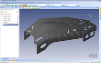 In the part displayed, the Design department has provided the Quality department with instructions to align the part for measurement using 3 points and 2 circles. The positions of the RPS points are provided in a text file and the circles have been identified visually.
Step 1: The operator loads the CAD part and prepares his nominal features for the RPS alignment.
Step 2: The user measures the 3 points and the 2 circles.
Step 3: The user creates his alignment. He defines the components of each feature that have a weight on the alignment. Here we see that CAM2 Q automatically checks for the points that only the Z direction is interesting.
Step 4: The part is pre-aligned to the measurement device.
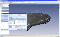 Step 5: The user identifies the points that were not initially taken within the home-in zone. He will re measure those points, using the Remeasure command.
Step 6: Since an alignment is active, the software now provides the user with a top view of the point and guidance to the correct location where he must measure the point.
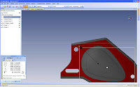 With 6 easy steps, the operator has now accurately aligned his part and can start measuring it.
Learn more about CAM2 Q.

